This railroad combines technologies from several hardware and software sources.
More than a controller, power supply and throttles, these technologies include Occupancy
Sensing, remote control of Turnouts and Signals, and Transponders (that identify
specific trains at specific places). Hardware vendors include Digitrax, Team
Digital, RRCirkits, Circuitron, Kato, and others.
The principle software driving our layout is a combination of JMRI and our own
MRRM code base. Of course, there is embedded software in most the
circuit boards also.
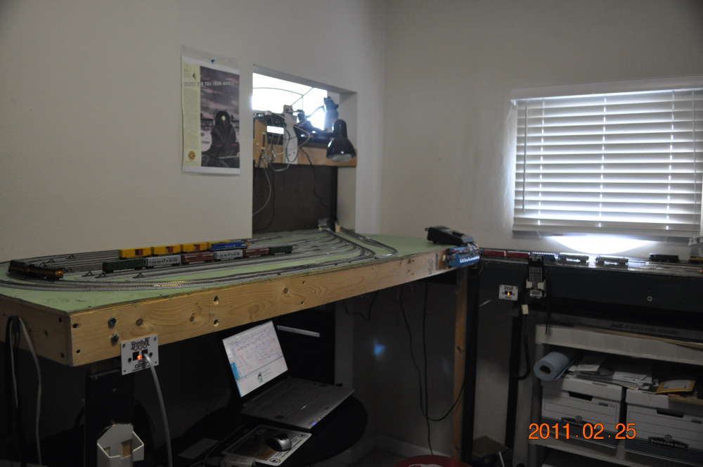
Beginning in 2009, the Keystone Division layout evolved
from a construction and basic trackwork project into an electronically and
software controlled system. Many of the sub-projects are summarized in the
paragraphs below. By the first quarter of 2010, the Keystone Division has
implemented most of these automation subprojects except for train automation
and Erie yard. We recently completed a project to install frog powering to the
many Peco turnouts installed. Another ongoing subproject is to significantly
detail the scenery (an early example).
One recently completed project was to find a suitable signal head housing for the many Digitrax SMBK signal posts that are now operational.
We are currently working on our
Robot Trains scripting generator. In
the future we will complete these sub-projects and add some more.
The Dispatcher System is virtually connected to the Loconet via WiFi LAN through
the Loconet Server which is directly connected to the Loconet. The Loconet
Server use the LoconetOverTcpLbServer feature in JMRI. This client/server
feature is extensible to other clients via the WiFi wireless LAN and may
eventually support remote clients via the Internet. Crew members may bring their
laptops with JMRI installed to observe the real time status if desired.
We currently use Digitrax and Powerline control interfaces to JMRI as indicated
in the JMRI PanelPro Server screen below:
For this snapshot we show the Loconet Locobuffer II Interface. For X10 Powerline we use a CM11, Insteon
2412S, or CP290 interface device.
For the Dispatcher Client we use the JMRI Panel Pro configuration shown below.
Upon start-up, we run several scripts to properly set the state of all
devices and logical objects used by JMRI. First we declare and initialize the
state of each physical and virtual (Internal) sensor used. We also set up a
number of control buttons described later. Next we load our Configuration File.
This file declares the many logical objects used by our layout under JMRI:
Turnout system and user names are declared for each JMRI remote controlled
turnout. We also declare the few manually controlled turnouts for Layout Panel
completeness. These names, addresses and other relevant data used for turnouts
are managed by MRRM which creates JMRI XML and Logix code snippets. MRRM reset and listener
scripts are also available. Since we now use PanelPro, listener
scripts are no longer used.
Sensor user names are declared. Currently these are resistance triggered block
occupancy detectors from Digitrax (BDL168, Se8C, BD4 devices) or from
RR-CirKits. The names, addresses and other relevant data used for sensors are
managed by MRRM and an MRRM created JMRI reset and a listener script are available.
Since we now use PanelPro, listener scripts are no longer used.
Reporter system and user names are declared. These Reporters are the Digitrax
proprietary transponder devices whereby a locomotive, having appropriate
functionality,will,when triggered, send its device address to the controlling
BDL168. The BDL168 then forwards that locomotive address to the JMRI program.
The comments field specifies the BDL circuit board and port address for the
reporter. These names, addresses and other relevant data used for transponders
are managed by MRRM and an MRRM created JMRI XMLcode snippet and listener script are available.
Since we now use PanelPro, listener scripts are no longer used.
Memory system names and user names are declared. Each memory object contains
persistent information written to or read from a logix or script created for the
layout. These names are managed by MRRM and an JMRI XML code snippet is available.
Internal sensor system names and user name are declared. These virtual sensors
are essentially binary variables made active or inactive via logix or scripts
created for the layout.
Timebase is declared
Block system names and user names are declared. Blocks describe a small part of
the layout topology and facilitate its management. Sensors within a Block are
identified. Turnouts with a Block are identified. Paths into and out of a Block
are specified. Blocks are used for JMRI dispatching and automated train running.
These names are managed by MRRM and a JMRI XML snippet is available.
Logix system names and user names are declared. The system name for each
Conditional logic is declared with its controlling Logix object.
Conditional system names and user names are declared. The rules governing each
conditional are specified. A Logix and its Conditionals are used to control CTC
like controls on our Dispatcher panels, to respond to related sensor changes, to
change related turnout states and to change related signal aspects.
Section system names and user names are declared. Sections are strings of
adjacent Blocks and are used to facilitate Dispatcher management of tracks and
turnouts. These names are managed by MRRM and a JMRI XML snippet is available.
Signal Head system names and user names are declared. Virtual and physical
signal heads are declared. Turnout addresses associated with control of physical
signal heads are declared. These names, addresses and other relevant data used
for turnouts are managed by MRRM and JMRI XML and Logix snippets, and reset and
listener scripts are available.Since we now use PanelPro,
listener scripts are no longer used.
Transit system names and user names are declared. Transits specify a path within
the layout for running a train. Transits specify a sequence of Sections.
Route system names and user names are declared
Audio system names and user names are declared
Layout Block system names and user names are declared. Related occupancy sensor
and memory objects are declared
Signal Element system names and user names are declared. Related turnout,
signals and sensors are specified.
Warrant system names and user names are declared. Warrants provide an
alternative JMRI dispatch management approach. Warrants specify a sequence of
blockOrder/block specifications which define a path within the layout.
OBlock system names and user names are declared. An Oblock identifies details of
a track path and related senors, turnouts and signals. OBlocks are used by
Warrants. These names are managed by MRRM and a JMRI XML snippet is available.
Lastly, the configuration file contains three Layout Panel specifications for
the two Dispatcher screens and the Real-Time Status Display. These
specifications are automatically created in the process of making a Layout
Editor panel within the JMRI PanelPro program.
The control buttons we create are summarized here
Block Table lists the Blocks used on the layout and its current occupany if any
Logix Table lists the Logix used by the layout.
Memory Table lists the Memory cells used by the layout and its current value
OBlock Table lists the OBlocks used by the layout. Paths and Portals are
included
Reporter Table lists the Reporters used by the layout and its current report
value if any
Section Table lists the Scetions used by the layout. The first and last Block
are identified.
Sensor Table lists the physical and virtual sensors used by the layout and its
current state
Signal Table lists the Signals used by the layout and the current state of each
signalhead is shown.
Transit Table lists the Transits used by the layout
Turnout Table lists the Turnouts used by the layout. The latest command issued
to each turnout is shown.
Reset Code IndiKators resets the Blinking Code light associated with Dispatcher
control of a turnout or associated signals.
Set Turnouts and Signals synchronizes the JMRI turnout and signal states to a
prescribed initial hardware status.
Set East Flow sets the traffic flow as West to East for all Signals - a test
case
Set West Flow sets the traffic flow as East to West for all Signals - a test
case
Set Go Flow sets the traffic flow to any for all signals - a test case
Set Stop Flow sets the traffic flow to stop for all signals - a test case
Networking
We are gradually adding networking to our configuration. The first major
networking added LoconetOverTcp between the TrainRoom Server and the Dispatcher
client. We have also tested this Server/Client method between the TrainRoom
Server and a Client that provides a RealTime status display in the Crew Lounge.
The key is syncing sensor, turnout and signal status in each JMRI copy running
concurrently.
In our first layout, we installed sensor, turnout, signal and reporter listeners
in some custom JMRI java additions plus some web servlet interface technology.
These listeners queued layout changes and timestamps within my JMRI code
additions. My servlets were invoked every 250 milliseconds by my MRRM software
to pull these layout changes from the queue in JMRI into my relational
datbase. This database then refreshed my custom panels and supported commanding
the layout turnout and signal changes from these clients.
We now are using multiple copies of JMRI, each with its own XML store, as opposed to a
centralized relational database. Loconet busses are relatively slow so there is
concern how far we can push this change in architecture. Hence minimizing
Loconet traffic when syncing up another client bears scrutiny.
We have also tested the WiThrottle Server and the WiThrottle-Lite app in my
iPhone - works fine! We have not stress tested it with other concurrent
clients yet..
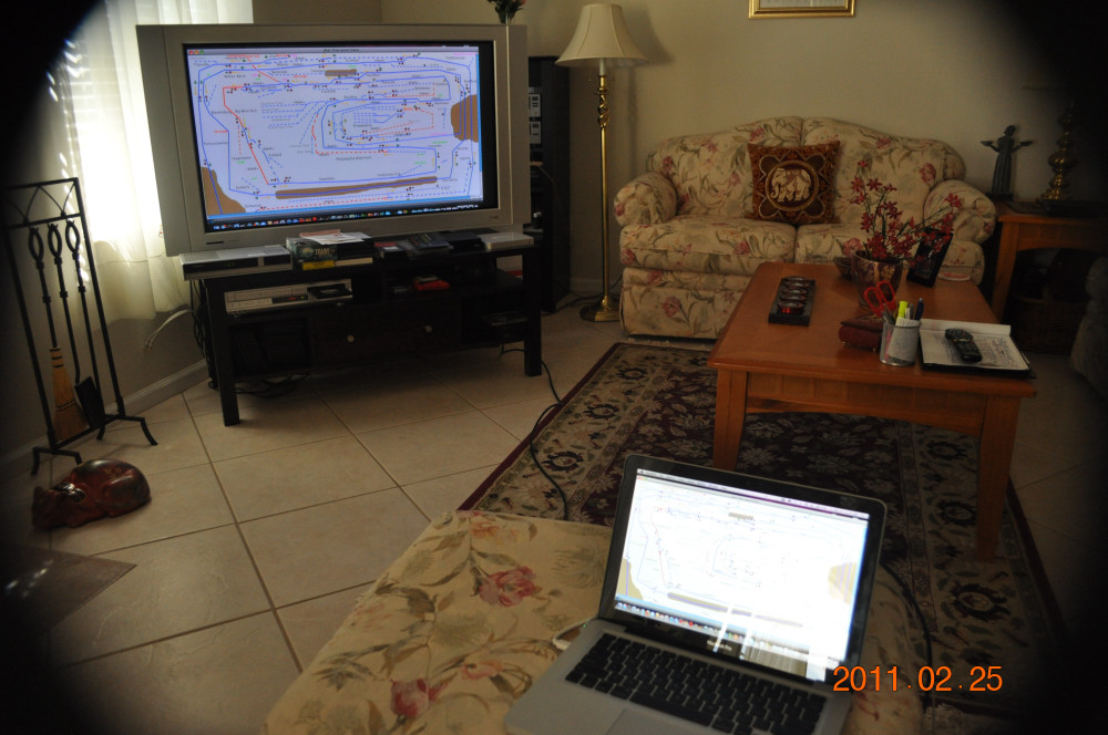
To allow the dispatcher to follow all trains, the current status is
displayed on a 'flat' point-to-point track diagram. Controls are installed to
allow the Dispatcher to manage all turnout states and signal aspects thereby
specifying permitted traffic flows for the entire layout.
We use our MRRM software to manage the large inventory of components comprising
the railroad and to support operations on the Keystone Division.
Inventory Management
Railroad work is created by the MRRM clock-based simulator of the industries using the
railroad. The specification for the simulator are created and stored in a
database.
The following selected Inventory data sets have been declared at this time for the R&C Keystone
Division:
Division Partners including
interchanging Railroads
Citytowns on the layout or off
the layout but involved in commerce
Commodity ladings and AAR car type assigned
to transport that commodity
Railroad Jobs
briefly defined - only a few are currently supported via MRRM. Supported jobs
are: Conductors, Engineers, Yardmasters, Dispatchers, Hostlers,
Freight Forwarders, Superintendent
Trading Partner
Prospect Summary for each commodity carried on the Keystone Division. The
buyer choices and the seller choices are derived from all Industries declared.
The MRRM simulator operates on Greenwich Mean Time (GMT). GMT is essentially the same as
the more recently minted Coordinated Universal Time (UTC). Each working industry is
the producer (Shipper) or consumer (Consignee) of one or more commodity
(Lading). The rate and amount of a given commodity produced or consumed for each
industry is user-defined in MRRM. MRRM advances GMT from a user defined baseline date
and time in one hour increments.
MRRM manages the Balance of declared buyer demand with supply production for
each commodity carried on the Keystone Division. Each Industry's activity is
manually adjusted until you achieve the volume and timliness desired.
Orders from Consignees are generated automatically from timing
declarations per commodity per industry, Orders are converted into Shipments when
a commodity selling industry has one or more carloads available for sale
according to its production timetable. If two or more industries have a load on
hand at the same moment then the shipment for the order is generated by the
seller chosen using a 'loads-on-hand weighted probabilty distribution'.
Instant Car
Inventory by track including Yards, Interchanges, and Industry track acting
as the homeyard for specifed cars.
Example list of shipments generated for my industries
A sample of an automatically created
Shipment from one of my Shippers to one of my Consignees
Car Queues for Shipments awaiting the transfer of needed AAR code cars from other
yards. If a Shipper's home yard does not instantly contain an empty car of the required
AAR-type that is
needed for a shipment, the home yard sends out an order for a suitable car from
another yard in its Division or from another Division if not available in the Home
Yard's Division. Typically a regular Way freight will add a Waybill
for this movement to its Manifest to move the car at the earliest opportunity.
Car Card sample
for Unit train of coal moved from Girardville Coal to Anthracite Exporters based
on Waybills generated for a Shipment.
Car Cards can be used for operations if preferred instead of Manifests. Waybills
define rolling stock moves based on industry orders/shipments and railroad
movement rules. Waybills are assigned to a manifest or to a card card deck
for every train run. Use the car card with a pocket that holds the specific
waybill for this car movement by this train.
We use a Digitrax DCS100 Command System as our DCC master device. A Digitrax
PM4 divides our layout into four power districts and reduces disruptions in one
area of the layout from incapacitating other areas of the layout. We expect to
add a 5th district for our Erie Yard (West Staging) and Pottsville Yard (East
Staging) area later this year. We will use
a Digitrax DB150 or DB100 device to power this section.
We use Digitrax radio throttles. Most are DT400 devices. We recently
added duplex radio capability to the layout and currently have three DT402
throttles.
A Fast Clock has been installed. We have not begun to have 'real'
operating sessions yet so we have some new experiences coming. Most of our large locomotive collection has had decoders installed in
them. Almost half of these locos have a Digitrax transponder enabled decoder option installed.
Digitrax DCS100 Command Station
Commands locomotive decoders via the Track Buss in most of the train
room and supports various devices on the Loconet
bus.
Digitrax DB150 Booster
Slave station that commands locomotive decoders via the Track Buss in
the two staging yards and a limited part of the layout room
Digitrax PM4
Four Power Districts from the Commend Station's Booster: Left, Center, Wye,
Right
sections of layout. A separate Booster is planned for Eire yard
Digitrax Se8C
Five Circuit Boards; capacities40 occupancy
sensors, 40 turnouts, 40 SPST switches; 160 signal post and 320 signal heads
Digitrax BDL168
Three Circuit Boards; capacities 48 occupancy sensors, 24 transponder readers
ARS1
WYE Reversing Trackage
Philadelphia Reverse Loop Trackage
West Staging Reverse Loop Trackage
Turntable support - tbd
Digitrax DS-52
Controls several Peco/Tortoise and Kato Turnouts
Team Digital SRC8
Controls 8 Tortoise Turnouts per circuit board;
two boards
Team Digital SMD8
Controls 8 Kato Turnouts per circuit board; two
boards
Digitrax Simplex and Duplex Radio Transceivers
Links Radio Throttles to Command Station
Digitrax Programming Track
Container Siding doubles as the programming track via DPDT switch.
About 80 Block Occupancy Sensors (BODs) have been installed. Each BOD creates a
track-turnout segment that will become active when a train is present in that
segment. Currently we can detect the presence of a locomotive and certain
cars - typically illuminated passenger cars or cars with resisters on
metal wheel axles.
We expect to install
insulated metal axles to many of our cars. A 10K Ohm surface mount resister will
be cemented to each axle and a conductive pen will complete the circuit across
the metal axle. With these modified axles our occupancy detectors will detect
the presence of such cars.
In 2015 we installed metal wheels and axles on all 'in-service'
cars and have added resisters to one axle of each caboose used. We used
axles from Fox Valley.
All active/inactive state changes of each BOD are reported to JMRI
listener software. The BOD change events are used by the signal logic to trigger
aspect changes. These change events also modify the track-turnout segment
'color' on the Dispatcher and Real-Time Status displays. An occupied or 'active' segment is Red; an unoccupied
or 'inactive' segment is Blue. Additionally, MRRM sensor
listeners that we install into JMRI will queue these occupancy events to the
MRRM server. MRRM will poll this queue about every 250 milliseconds to update
our monitoring system.
Each Se8c supports 8 BODs via two remote Digitrax BD4 circuit boards. We
installed remote RR-CirKit boards to Se8C ports to provide BODs in special cases
such Reverse Loop/Wye track segments. The five Se8c circuit boards support
a total of 40 BODs. We
also have 3 Digitrax BDL168 circuit boards installed. Each of these circuit
boards support 16 BODs or a total of 48 BODs.
To see some photos of the block occupancy wiring construction click
here.
We now have over one hundred turnouts on the layout and we have installed
computer control for more than 60 turnouts. Most of these are Peco turnouts
using a Tortoise slow motion machine driven by a one of 8 ports on one of our 5
Digitrax Se8c circuit boards or 12 dual port Digitrax DS52 circuit boards.
Another eight of our Tortoises are driven by a Team Digital SRC8 circuit board.
We also have six Kato turnouts with built-in switching machines driven by
Digitrax DS51K1 circuits. We also have one Kato double crossover driven by a
Digitrax DS52 circuit board. All turnouts are controllable from the JMRI
software or from Digitrax throttles. Our JMRI Dispatcher panels can command
these turnouts. There are no fascii panel switches at this time. However, the
needed supporting control electronics are preinstalled for 40 such future fascia
switches (from 5 Se8C circuit boards).
Erie Yard uses Kato track and turnouts. Automation is under construction.
Pottsville yard is mostly Peco turnouts with some tortoises now installed.
Awaiting new DCC controlled turntable product. Automation is under construction.
MRRM can also command these turnouts using our Web Services interface
to JMRI.
Additionally, MRRM turnout listeners that we install into JMRI will queue
turnout change events to the MRRM server. MRRM will poll this queue about every
250 milliseconds to update our system.
To improve electrical continuity on mainline turnouts, we have powered the frogs
on Peco turnouts using the SPST switches built into
the tortoises. Note: The Peco turnout springs DO have to be removed from the
Peco turnouts to avoid shorts due to turnout movement becoming out of sync,
however briefly, with
Tortoise movement and SPST switch closure. The time and motion associated with
the turnout and tortoise is very important to avoiding shorts.
For the remaining tortoise driven turnouts, we still rely soley on the pressure
that the tortoise exerts on the points. Eventually all frogs will likely need to be
powered for reliable operations.
The Kato turnouts rely on Kato's design for reliable electrical continuity.
To see some photos of the turnout wiring construction click
here.
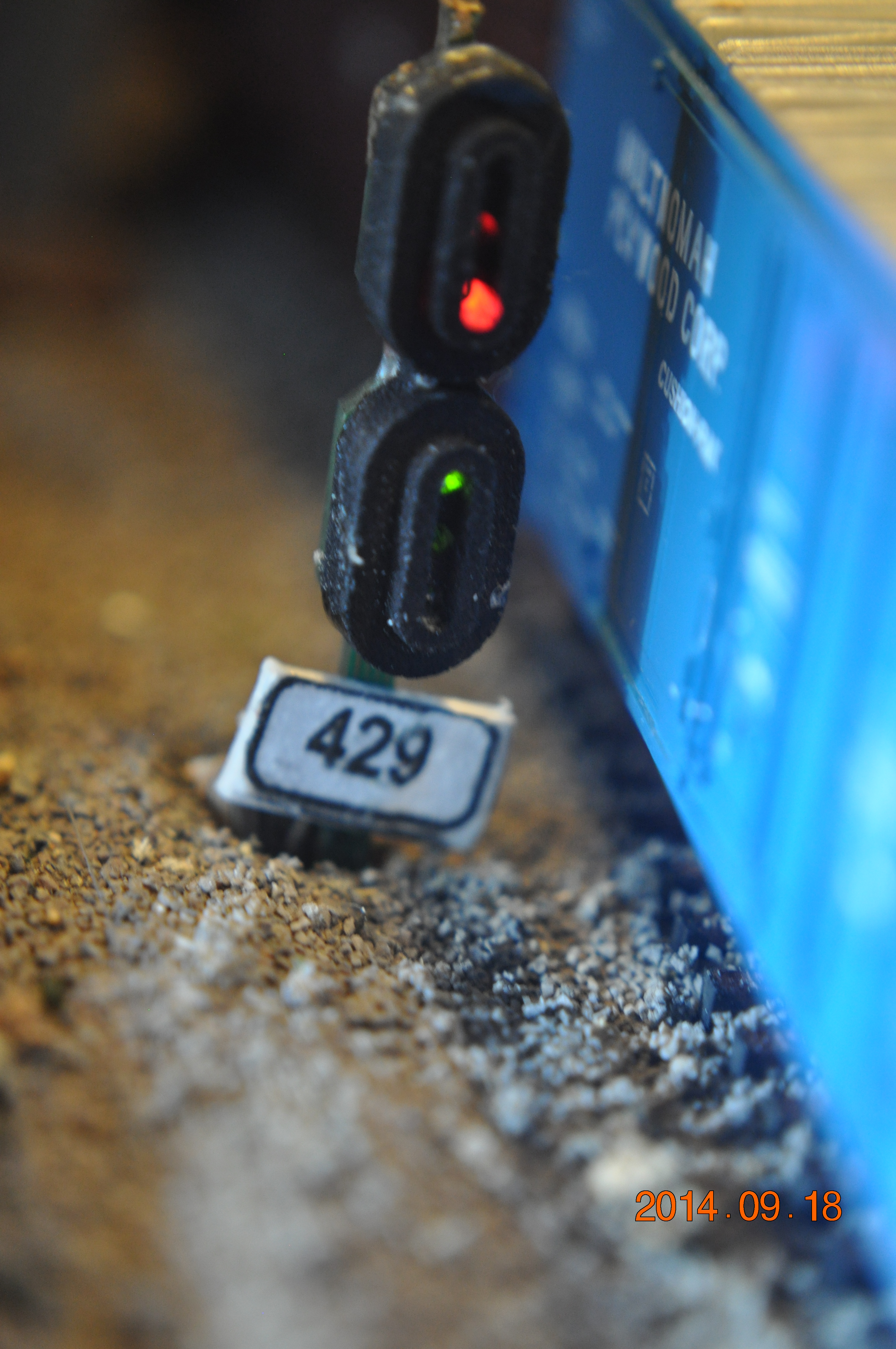
We currentlky have installed 138 three light signal heads on the layout (404 LEDs). At this
time, all signals are based on Digitrax SMBK head over head posts which are a
good size for our N scale railroad.
We are still looking
for a good dress-up kit for these Digitrax signal posts. We are looking into a
RepRap machine to design a dress-up kit. Any ideas from readers would be
welcomed.
To dress up the Digitrax signal heads, we
created our first 3D printing project in 2014.
We settled on two styles for the
masts: two groups of three hooded single lamps and two groups of one surrounded
triple lamps. They are shown here:
The number placard on the mast identifies the DCC address of the first of four
sequential addresses that control the aspects.
All signals are driven by Digitrax Se8C circuit boards. Each board drives 4
heads via each of eight ribbon cable or 32 heads per circuit board. We have
five
Se8c circuit boards installed supporting our signals at this time. All signal heads are
driven by JMRI software. Each signal is programmed using 'simple signalling
rules' and Logix installed into JMRI.. Each signal head is controlled by a pair of 'turnout' addresses. One
must plan the turnout number address space carefully in conjunction with the constraints
imposed by the various circuit boards.Here are my
accessory address range standards and
sensor addess standards for my Digitrrax controlled layout.
MRRM can also command these signals using our Web Services interface.
Additionally, MRRM signal listeners that we install into JMRI will queue signal
change events to the MRRM server. MRRM will poll this queue about every 250
milliseconds to update our system.
To see some photos of the signal wiring construction click
here.
See the next video for a cascading signal test of the
operating signaling system with the shrouds and placards installed on
the signal masts.
A Transponder is a device implemented as a Digitrax proprietary extension to
the NMRA DCC specification. Locomotives with certain Digitrax decoders have the
capability to transmit their 'Address' to a Digitrax 'Reader' or
tranponder installed on a given
track-turnout block segment. These addresses are forwarded to JMRI listener software.
The address is shown on the JMRI based Dispatcher and Real-Time Status displays
we have built with JMRI PanelPro. When, say, loco #3424 enters a transponder section, the message
displayed is "3424 enter" .When that loco leaves the segment, it displays "3424
exit".
MRRM tranponder listeners that we install into JMRI will queue
decoder address enter and exit events to the MRRM server. MRRM will poll this
queue about every 250 milliseconds to update our system. The decoder's address
and state values are forwarded to the MRRM software to link the locomotive
to an active manifest and set of waybills. Thus we know where the train is going
to next and what cars are currently on the train - among other things.
Each BDL168 can support a pair of quad segment transponders. These four port
circuits are known as Digitrax RX4 devices. Each of the eight RX devices
supports one track-turnout segment whose BOD is also supported by the BDL168
circuit board. The RX sends a signal on the track segment during the quiescient period
between DCC packets. If a transponder equipped loco decoder senses the RX signal
it 'transponds' its address back to the RX and thus to the BDL168 and thus to
the JMRI listener on the Loconet bus.
We currently support 20 transponders
and 8 to 12 more are under development. Most are assigned to key mainline
or bypass track-turnout segments.
To see some photos of the transponder wiring construction click
here.
We have experimented with the two tools built into JMRI for automated control as
well as the JMRI Robothrottle scripts with mixed results. We are currently building a
script generator into MRRM to create automated train scripts. This script
builder will replace the one we built into the pre-2005 version of MRRM. We
expect to control these scripts via a custom layout panel that is under
development.
We have created an automated train scripting tool based on the sensors, signals,
turnouts, speed limits etceteras. Since they obey "the rules", we can have human
engineers and robot engineers on the railroad at the same time. Check the
Robot Trains page for examples.
We have installed 10 Miller Electronics electroluminescent billboards. We also
installed 8 ITCC sound generating devices throughout the layout. Two operating oil
pumps are installed. A flashing sequence lighted radio tower is installed. A
Windmill is installed - we saw many of these during a recent trip on the
Appalachian Mountains. A Faller Mine was built but operation is balky. Many
more lights and animated devices are planned.
 This railroad combines technologies from several hardware and software sources.
More than a controller, power supply and throttles, these technologies include Occupancy
Sensing, remote control of Turnouts and Signals, and Transponders (that identify
specific trains at specific places). Hardware vendors include Digitrax, Team
Digital, RRCirkits, Circuitron, Kato, and others.
The principle software driving our layout is a combination of JMRI and our own
MRRM code base. Of course, there is embedded software in most the
circuit boards also.
This railroad combines technologies from several hardware and software sources.
More than a controller, power supply and throttles, these technologies include Occupancy
Sensing, remote control of Turnouts and Signals, and Transponders (that identify
specific trains at specific places). Hardware vendors include Digitrax, Team
Digital, RRCirkits, Circuitron, Kato, and others.
The principle software driving our layout is a combination of JMRI and our own
MRRM code base. Of course, there is embedded software in most the
circuit boards also.


