Purpose | Screen Images | Data Description | Function Descriptions | How to Use
MRRM supports three types of Panel: Track Panels, Toggle Subpanels, and Mainline Subpanels.
Track Panels display some of the tracks in some part of your layout, The display can include track, turnouts, BODs, signals, and landmarks. The current state of turnouts, BODs and signals can be automatically updated and displayed based on the current information in the database. Track Panels are used on Dispatcher Panel Displays or Fascia Displays. Currently, up to two Dispatcher and two Fascia concurrent Display panels can be configured with MRRM. The Dispatcher tabpage can display two Panels per screen if your computer power and operating system is adequate. Also, the HyperThrottle Engineer Cab can support one Track Panel per cab.
Toggle Subpanels provide soft toggle switches linked to turnouts on a Track Panel. Turnouts can be commanded by flipping its associated Toggle. Route turnouts can also be invoked from a Toggle Subpanel. Dispatcher Panels always have Toggle Subpanels. Toggle Subpanels are optional on Fascia Track Panels and are not supported on Engineer Cab Track Panels.
Mainline Panels present a string of small icons, each representing one Track Panel, across the top of a Dispatcher display. Rollover tags indicate the name of the Track Panel that the icon represents. Double-clicking the icon causes the associated Track Panel and Toggle Subpanel to be displayed on the Dispatcher screen. In this way your entire railroad is always available, from East (right) to West (left). Using a mouse, you can quickly view the status of any track, signal, turnout (or supported sensor) on your railroad.
The following figure shows the panel editor in trackwork mode. This mode is used to create an abstraction of part of your layout, overlaid with signals, BODs, transponders, and landmark information.
This figure shows the basic icons used to paint a track panel. Not all possible icons are shown, just the ones most frequently used while painting. For example, a signal color could be "black" if it is set to unknown in the database. A turnout would have a question mark imposed on it if its state were unknown. An 'X' would be superimposed on a turnout if it were set as 'Failed'. Mouse rollovers can be used on the palette in the program to indicate its purpose.
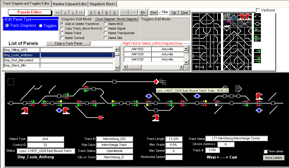
The Panels Editor is used to create or edit track panels and toggles subpanels (see radio buttons to select which type to work on. In the following figure we have selected the Track Diagrams edit mode. This is indicated by the 'Diagram Edit Mode function options being enabled (e.g. 'Name Track')
The figure shows the "Disp_Louis_Anthony" track panel. As you roll the mouse over an icon a short popup descriptor will display. The red box with black arrowhead shows which train is occupying this BOD and which direction it is currently heading toward. Note that the information is not simple the address of a decoder but a specific train and its current manifest. Additional data about the icon will be displayed in the lower portion of the track panel. The small checkbox in the upper right corner of the panel activates a timer to update the displayed status of BODs, Turnouts and Signals. All track panels display West on the left and East on the right side of the panel.
The next figure shows a track panel with its Toggles Subpanel in place.
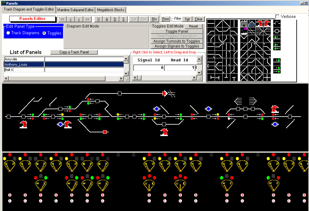
The detailed rollover data still works but it is covered when the toggles are displayed. Double clicking the toggles subpanel minimizes it to the bottom of the screen revealing the detailed data again. Double click the minimized toggles subpanel to restore its size and location.
If the dot above a toggle is red, then the turnout control and/or the signal flow control can be displayed. Right clicking this dot brings up options. The dark gray dot indicates that the 'panel position' is not in use on this panel simulating a partially pre-punched 'metal' panel back.
The toggle immediately below the aforementioned dot is a control for a turnout on the track schematic panel above the toggle panel. The turnoout toggle switches between 'Normal' (Closed) and 'Reverse' (Thrown). The 'led' above 'Normal' goes to Yellow when turnout is closed and gray when turnout is thrown. Similarly the led above 'reverse' goes red when turnout is thrown and gray when turnout is closed.
The toggle below the turnout toggle position is the signal flow control. Thes controls allow the dispatcher to grant single mainline or shared track access to trains either Westbound or Eastbound Up to four signal heads can be influenced by each signal flow control. This control has three positions: left (W), center, and right (E). When in the left position, Westbound traffic is Not Restricted but Eastbound traffic is Restricted. When in the right position, Eastbound traffic is Not Restricted but Westbound traffic is Restricted. When in the center position, traffic in both directions is restricted - while the dispatcher resolves the next direction flow. The left and right leds are red when resrtricted and green when not restricted. The center led is gray when either left or right flow is selected and red when all restricted center position is in effect.
The 'button' with the letter 'S' om it is the Start-Code button. After the dispatcher changes a turnout or signal flow control, the commands are not immediately sent to the layout. To command the layout, you press (click!) the Start-Code button. It is shown as red with white 'S' when pressed and until the command is sent after which the button reverts to whit with red 'S'.
The white button with 'L' on it below the Start-Code button is the Lock command. This button will be used to disable local crew (non-dispatcher) from altering of a turnout aspect on the layout when this feature becomes available.
If you check a small checkbox in the middle right side (not visible here) of the toggles subpanel, the route table is displayed. Doubled clicking a route causes all turnouts in the route to be commanded.
If the track panel checkbox is set, the visual state of the turnout will be changed on the next status check done for this track panel. If the same turnout is on another track panel, it will be updated also. If you have a multi-user database version of MRRM, you could have several Dispatcher or Fascia displays concurrently updated. Large private or club layouts could use multiple, distributed, soft fascia displays instead of handmade, hardwired types used today.
Mainline Sub-Panel
The next figure shows the mainline subpanel editor. The mainline subpanels are only shown on the Dispatcher's Track Panels. The mainline subpanels give the Dispatcher quick access to the status of all track, turnouts, BODs and signals on the layout.
Right clicking on a line segment of either line allows you to insert a Track Panel link. These Track Panel links are indicated by the small rectangles shown on the line. In operation, if you double click a rectangle on the upper line, the track panel will pop up just below the second mainline line. Double clicking a rectangle icon on the second line pops up a secondary track panel below the top track panel.
My layout has a single track mainline, hence there are gaps shown in the second row of mainline icons.
Track Diagram Mouse Rollover Data
Object Type - track, bod, signal, turnout, transponder
Control ID - identifier for the specified object type
Status - depends on object type
BOD - Unoccupied or Occupied and if tracking locos, the loco rolling stock inventory ID and its movement direction
Signal - Inactive or Active
Turnout - Closed or Thrown
Transponder - last seen Rolling Stock ID and whether Entering or Leaving transponder's zone
Track ID - alphanumeric ID of the track at the mouse position
Rail Class - Industrial, Main Line, Branch Line, Bypass, Yard, Interchange
Track Status - Track is either Operational or Out of Service
City or Town - city or town where track is located
Track Length - lengthof track in prototype length
Max Grade - zero to 5.9%
Max Speed - speed limit on this track
Restricted Speed - restricted speed on this track
Track Name - long name decription of the track
Device Address - Turnout, switch, sensor, transponder address, if touched by mouse
Track # - Track # if used
Toggle Diagram Mouse Rollover Data
Toggle Device # - one up unique toggle number for this toggle panel
Toggle State - if toggle is a turnout, then Closed or Thrown
Toggle Lock Present - whether or not a toggle lock is present on thsi toggle
Lock State - Green or Red
Type of Device Controlled - Turnout only at this time
Device Controlled ID - if a turnout, the turnout identifier (not the addres)
Toggle Button - create a new toggle
Lines Button - show or hide horizontal line on the toggles panel
Edit Panel Type
Track Diagrams - select this radio button to edit a track diagram
Toggles - select this radio button to edit a toggles diagram
Copy a Track Panel - create a new apnel based on the selected panel
Verbose - tell more about actions underway while learning to use the editor
Diagram Edit Mode - (when active)
Close Diagram - remove the track diagram from the editor screen
Reset Diagram - remove all objects on the current track diagram
Add or Delete Track - use to load and then create/change a track diagram
Copy or Delete Track - copy an object on the diagram and place it elsewhere on the diagram
Name Track - shows all of your track/siding segments; drag and drop name to a track segment or a track hosting a Turnout, BOD, Signal or transponder device
Name Turnout - shows all of your turnouts; drag and drop a turnout ID to a turnout on the diagram
Name BOD - shows all of your BODs; drag and drop a BOD ID to a BOD on the diagram
Name Signal - shows all of your Signal Heads; drag and drop a Signal Head ID to a Signal Mast on the diagram
Name Transponder - shows all of your Transponders; drag and drop a Transponder ID to a Transponder on the diagram
Name Site -shows all of your Building Sites; drag and drop a Building ID to a Site on the diagram
Checkbox in upper right of track diagram - when checked, this box periodically polls the MRRM database for updates to the objects on the panel
Toggles Edit Mode
Reset - clears all objects on the current toggles panel
Toggle Panel - Loads the selectesd toggle panel
Test Toggles Operation - Place the current or selected toggle panel into operational testing mode
Assign Turnouts to Toggles - show your turnouts; drag and drop a turnout ID to a toggle object
Checkbox in upper right of toggles diagram - show the routes availavle on your layout; double click one to execute it
Create as many track and toggle diagrams as you need to control or monitor portions of your network. Create a single Dispatcher's subpanel of your signle or double mainline linkage to the track and toggle diagrams.
Engineer or Fascia Track Diagrams might include more layout details than a Dispatcher diagram of the same region. A multi-user version of MRRM will support multiple concurrent PCs sharing a single database containing the current status of all BODs, Turnoouts, Signals, Transponders, and other supported components. The MRRM database is synchronized to the layout via feedback messages whether the commands were generated from within MRRM or via other layout devices such as throttles or hard wired fascia buttons which communicate their commands to layout network listeners.
